Your smartphone has become the second brain of your car. From real-time navigation and wireless CarPlay to streaming and voice assistants, it works at full throttle every time you drive. Yet many users still complain about overheating, slow charging, or mysterious “Key Not Detected” errors inside modern vehicles.
The shift from traditional Qi to Qi2 is transforming in-car wireless charging with magnetic alignment and standardized 15W power delivery. At the same time, new research shows that strong magnet arrays can interfere with pacemakers, smart keys, and even digital compasses if used carelessly.
In this article, you will explore the physics behind magnetic power transfer, real-world thermal test data, FDA safety guidance, automotive regulations, and the rise of active cooling technologies like Peltier modules. By the end, you will understand how to choose the safest and most future-proof Qi2 car charger for 2026 and beyond.
- Why Smartphones Became the “Second Brain” of Modern Vehicles
- From Qi to Qi2: How Magnetic Power Profile (MPP) Solves the Alignment Problem
- The Physics of Misalignment, Energy Loss, and Heat Generation in Moving Cars
- Global Qi2 Adoption in 2025–2026: 1,200+ Certified Products and 4 Billion Device Forecasts
- Automakers Embrace Qi2: Nissan’s 2026 Integration and the OEM Turning Point
- The “Triple Heat” Challenge: Ambient Solar Load, SoC Processing, and Inductive Charging
- Active Cooling Explained: Fan-Based Systems vs. Peltier (Thermoelectric) Modules
- Thermal Test Data: How Cooling Directly Impacts Sustained 15W Charging Speeds
- Magnetic Interference and Pacemakers: What FDA and Clinical Studies Reveal
- Smart Key, GPS, and Digital Compass Interference Inside Modern Cars
- Legal and Visibility Considerations When Mounting a Phone in Your Vehicle
- 2026 Buyer’s Checklist: Qi2 Certification, Cooling Requirements, and Safe Placement Strategies
- 参考文献
Why Smartphones Became the “Second Brain” of Modern Vehicles
Over the past decade, the relationship between cars and smartphones has fundamentally changed. What was once a simple Bluetooth connection for calls or music has evolved into a deep technological integration where the smartphone now functions as a vehicle’s cognitive extension. With the widespread adoption of Apple CarPlay and Android Auto, drivers increasingly rely on their phones for navigation, communication, media, and even voice-driven control. In practical terms, the smartphone has become the “second brain” of the modern vehicle.
This shift is not anecdotal but structural. According to industry reports from the Wireless Power Consortium and market research firms, the rapid expansion of Qi2-certified devices—projected to reach billions of units over the coming years—reflects how central smartphones have become in daily mobility. Automakers are responding accordingly. Nissan, for example, announced Qi2 integration in its 2026 U.S. models such as the Pathfinder and Murano, signaling that manufacturers now design interiors with the smartphone as a core interface rather than an accessory.
The transformation can be understood by comparing the traditional in-car information architecture with today’s smartphone-centric model.
| Function | Traditional Vehicle System | Smartphone-Driven System |
|---|---|---|
| Navigation | Built-in map database, periodic updates | Real-time cloud-based maps with live traffic |
| Communication | Hands-free calling module | Messaging apps, VoIP, voice assistants |
| Software Updates | Dealer-based updates | Continuous app and OS updates |
Navigation is the clearest example. Modern drivers depend on real-time traffic rerouting, crowd-sourced incident data, and cloud-based map corrections. These capabilities exceed the static map databases traditionally embedded in infotainment systems. The smartphone’s system-on-chip processes GPS signals continuously while maintaining 4G or 5G connectivity, effectively acting as an external computational unit for the vehicle.
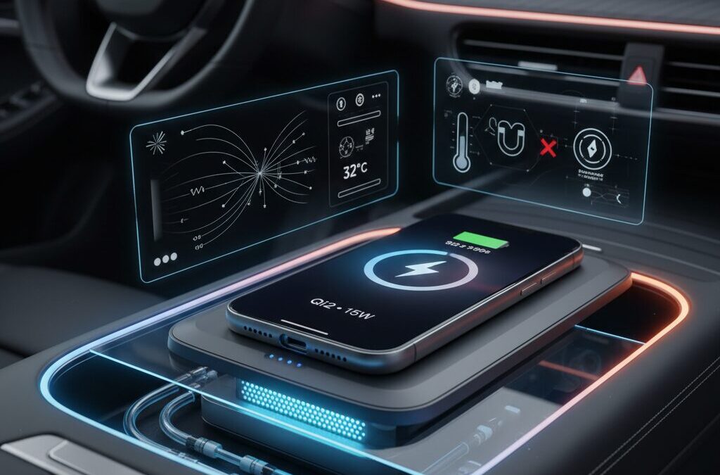
However, a “second brain” must remain powered and stable. This is where wireless charging—particularly the Qi2 Magnetic Power Profile—becomes strategically important. By physically aligning coils with magnetic arrays, Qi2 reduces energy loss and heat generation compared with earlier Qi implementations. The result is not just convenience but reliability. A misaligned or overheated phone can throttle performance, dim its display, or suspend charging, directly impacting navigation visibility and connectivity during driving.
Research highlighted by Chargerlab and other testing bodies shows that thermal buildup during wireless charging can trigger output reduction within minutes if alignment or cooling is inadequate. In a mobility context, that means the “second brain” may slow down precisely when high processing loads—GPS tracking, map rendering, and data streaming—are required simultaneously.
This convergence of mobility and mobile computing marks a paradigm shift. Vehicles increasingly provide the physical platform—power supply, mounting infrastructure, cabin integration—while smartphones provide the intelligence layer. As Qi2 adoption accelerates and automakers integrate certified charging systems directly into dashboards and consoles, the boundary between car and phone becomes less visible.
The modern vehicle is no longer an isolated machine with embedded electronics; it is an ecosystem node powered by the smartphone in your pocket. Understanding this transformation is essential for anyone evaluating in-car charging technology, magnetic mounts, or next-generation infotainment strategies.
From Qi to Qi2: How Magnetic Power Profile (MPP) Solves the Alignment Problem
Traditional Qi wireless charging was built on a simple physical principle: electromagnetic induction. However, in real-world environments such as a moving vehicle, this elegant theory often collided with a harsh reality—misalignment.
In conventional Qi (BPP/EPP), charging efficiency depends heavily on how precisely the transmitter coil and receiver coil overlap. Even a few millimeters of lateral shift can reduce the coupling coefficient, forcing the system to increase current to maintain power delivery.
This directly translates into higher I²R losses, more heat generation, and unstable charging speeds. In a vibrating car cabin, consistently hitting the “sweet spot” was nearly impossible.
Why Alignment Matters in Inductive Charging
| Factor | Well Aligned | Misaligned |
|---|---|---|
| Coupling coefficient (k) | High | Reduced |
| Required current | Lower | Higher |
| Heat generation | Controlled | Increased |
| Charging stability | Stable output | Throttling likely |
As documented in multiple charging lab measurements, once coil alignment degrades, leakage flux increases and eddy currents can form in nearby conductive components. The result is familiar to many drivers: a warm phone and barely rising battery percentage.
Qi2 addresses this structural weakness through the Magnetic Power Profile (MPP). Rather than relying on user precision, MPP integrates a precisely defined magnet array around the power transmitter operating at 360 kHz.
These magnets physically guide the smartphone into the optimal charging position. Alignment is no longer a matter of chance—it becomes mechanically enforced.
According to the Wireless Power Consortium, Qi2 is built upon Apple’s MagSafe architecture, standardizing magnetic positioning across brands. This is not simply “adding magnets.” It is a tightly specified magnetic geometry that guarantees repeatable coil centering.
The benefits are immediate and measurable. With alignment stabilized, coupling efficiency remains near its designed maximum. That means less compensatory current, reduced thermal stress, and more consistent 15W power delivery across certified devices.
Another critical advantage is enhanced Foreign Object Detection (FOD). Because the receiver’s position is predictable, the transmitter can more accurately detect abnormal impedance signatures caused by coins or keys trapped between surfaces. This improves safety margins, especially in confined automotive trays.
Market data reinforces the significance of this shift. As reported in WPC’s 2025 research and Business Wire coverage of Qi2 adoption, more than 1,200 Qi2-certified products entered the market in 2025 alone. This rapid scaling reflects industry confidence in MPP as a foundational solution—not a cosmetic upgrade.
For automotive environments in particular, where vibration and user distraction are unavoidable, MPP transforms wireless charging from a convenience feature into a reliable power interface. The magnetic ring ensures that every mount action reproduces lab-grade alignment conditions.
Qi2’s Magnetic Power Profile solves the alignment problem by turning physics from a limitation into a controlled variable. Instead of fighting misalignment with higher current and heat, it prevents misalignment altogether.
This shift—from probabilistic placement to deterministic positioning—is the true leap from Qi to Qi2.
The Physics of Misalignment, Energy Loss, and Heat Generation in Moving Cars
When a car is in motion, wireless charging no longer operates in a static laboratory condition. It becomes a dynamic electromagnetic system constantly challenged by vibration, micro-shifts, and mechanical instability. Even a few millimeters of coil misalignment significantly alter magnetic coupling efficiency, and this is where physics directly translates into heat and energy waste.
According to the Wireless Power Consortium’s technical framework for Qi and Qi2 systems, inductive charging efficiency depends heavily on the coupling coefficient between transmitter and receiver coils. In ideal alignment, magnetic flux linkage is maximized. In a moving vehicle, however, lateral displacement and tilt reduce this coefficient, forcing the system to compensate electrically.
Lower coupling means higher current is required to deliver the same power, and because resistive losses follow the I²R law, heat generation increases exponentially rather than linearly.
| Condition | Coupling Efficiency | Thermal Impact |
|---|---|---|
| Precise coil alignment | High (near optimal k) | Minimal resistive heating |
| Minor lateral shift (few mm) | Moderately reduced | Increased I²R losses |
| Significant vibration or tilt | Low coupling | Excess heat + power throttling |
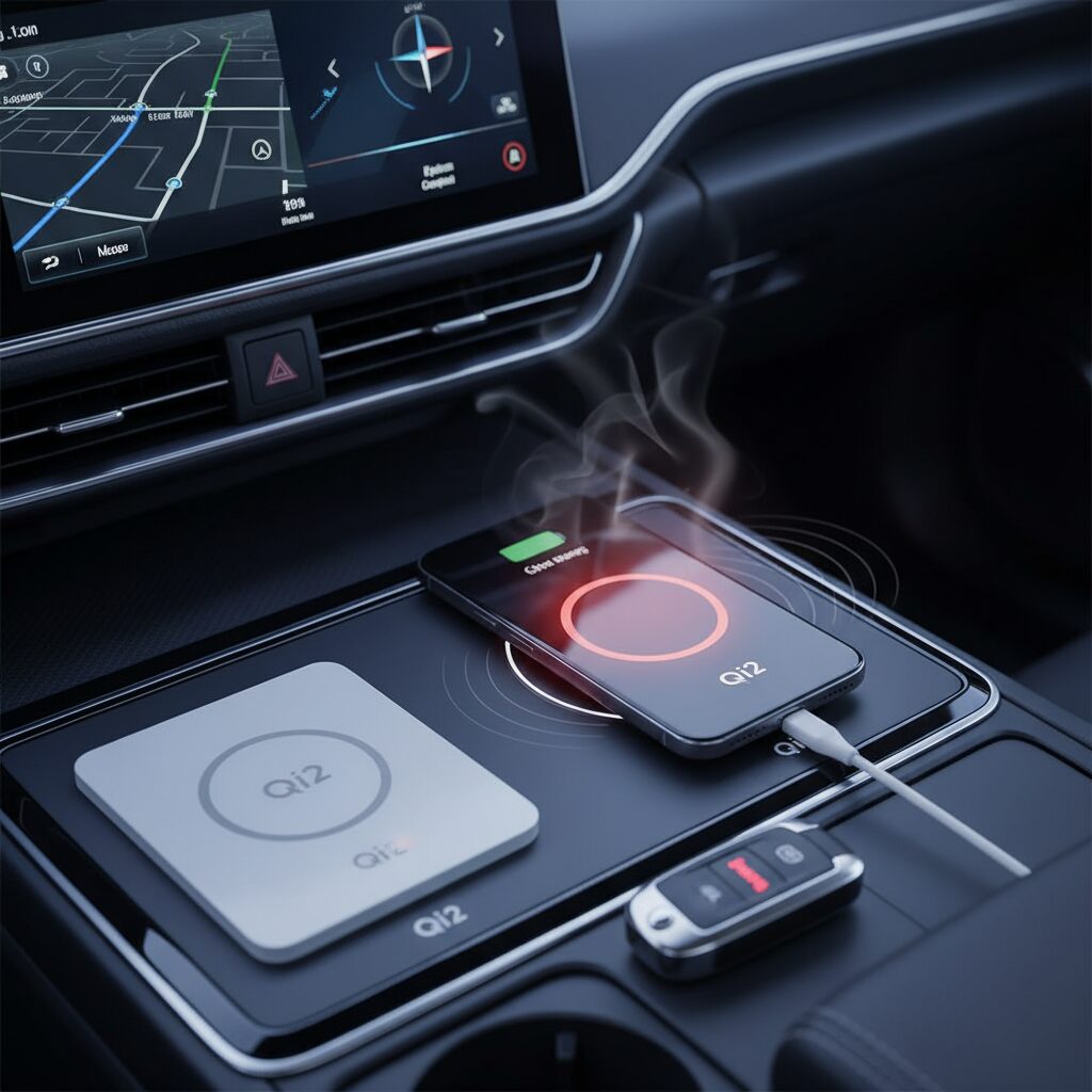
In practical terms, when a smartphone shifts slightly on a conventional Qi pad during cornering or braking, the charger compensates by raising coil current. Chargerlab’s controlled thermal testing of MagSafe systems shows that temperature rises above 40°C can occur within minutes when alignment is imperfect and cooling is absent. This is not a design flaw but a predictable thermodynamic outcome.
Another overlooked factor is eddy current formation. When magnetic flux leaks due to misalignment, it interacts with conductive components inside the phone—shielding layers, camera modules, or internal ground planes. These parasitic currents convert electromagnetic energy directly into heat. The user experiences this as “the phone getting hot but charging slowly.”
Energy that fails to couple magnetically does not disappear—it transforms into thermal loss.
Vehicle motion amplifies this effect through three physical mechanisms. First, mechanical vibration creates continuous micro-adjustments in coil distance (the Z-gap). Even sub-millimeter vertical oscillations change magnetic field strength. Second, acceleration forces can introduce rotational misalignment, reducing the effective overlapping coil area. Third, thermal expansion from prior heating can subtly alter structural tolerances, compounding inefficiency over time.
The move from traditional Qi to Qi2’s Magnetic Power Profile directly addresses this physics constraint. By using a defined magnet array to force geometric alignment, Qi2 minimizes lateral drift during motion. The result is not merely convenience but measurable thermodynamic stabilization. Business Wire’s 2026 coverage of Qi2 adoption highlights efficiency consistency as a primary engineering objective of the new standard.
From a systems perspective, this matters because wireless charging is already less efficient than wired charging. While wired solutions can exceed 90% efficiency under optimal conditions, inductive systems operate lower due to conversion stages and magnetic transfer losses. When misalignment is introduced, effective efficiency drops further, and excess energy converts into heat within both the charger coil and the smartphone’s power management circuitry.
Heat generation follows a compounding pathway:
Reduced magnetic coupling leads to increased transmitter current.
Increased current raises resistive losses in copper windings.
Elevated temperature increases electrical resistance further, reinforcing the cycle.
This positive feedback loop explains why temperature spikes can accelerate quickly inside a parked or sunlit vehicle. Once internal battery temperature approaches the 35–40°C protection threshold commonly referenced in lithium-ion safety design literature, the device activates thermal throttling. Charging power is reduced, sometimes from 15W down to 5W or lower, stabilizing temperature but extending charging time dramatically.
The National Institutes of Health has published research indicating that lithium-ion degradation accelerates significantly above 45°C. In a moving car where ambient temperatures may already exceed 50°C in summer conditions, misalignment-induced heat becomes a meaningful contributor to long-term battery wear.
In other words, misalignment is not just an efficiency issue—it is a battery longevity issue.
There is also an electromagnetic field distribution consequence. Proper alignment concentrates flux lines within the intended receiver geometry. Misalignment causes flux spreading, increasing stray field interaction with nearby metallic components. This not only wastes energy but can slightly elevate electromagnetic noise in the immediate environment, though within regulatory compliance limits for certified devices.
One subtle but important insight is that vehicle motion transforms wireless charging from a static magnetic coupling problem into a dynamic control systems problem. Power controllers must constantly negotiate between delivering target wattage and preventing overheating. Modern Qi2 firmware dynamically adjusts frequency and current to maintain stability, but physics ultimately defines the ceiling.
Therefore, in a moving vehicle, mechanical alignment stability directly determines electrical efficiency and thermal output. Magnetic locking mechanisms in Qi2 systems reduce micro-slippage, preserving coupling coefficient integrity even under acceleration or vibration.
The smoother the magnetic geometry, the lower the entropy introduced into the system.
For gadget enthusiasts evaluating car chargers, understanding this chain—from misalignment to energy loss to heat generation—clarifies why magnetic alignment is more than a design aesthetic. It is a thermodynamic optimization strategy grounded in electromagnetic theory. In motion, physics is unforgiving, and only precise alignment keeps energy flowing where it should: into the battery, not into wasted heat.
Global Qi2 Adoption in 2025–2026: 1,200+ Certified Products and 4 Billion Device Forecasts
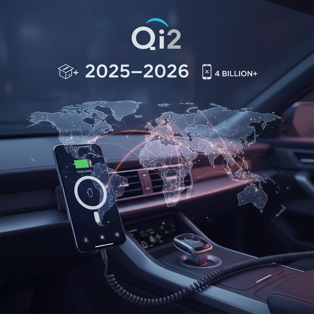
The scale of Qi2 adoption in 2025–2026 is unprecedented in the history of wireless charging. According to the Wireless Power Consortium (WPC) and coverage reported by Business Wire, more than 1,200 Qi2-certified products were approved in 2025 alone, spanning smartphones, transmitters, receivers, and in-vehicle charging systems.
This is not incremental growth. It represents a structural shift toward a unified magnetic alignment standard built around the Magnetic Power Profile (MPP). The certification surge signals that manufacturers are no longer experimenting with magnetic wireless charging—they are standardizing it.
2025 marked the inflection point where Qi2 moved from early adoption to ecosystem scale.
Key indicators reported by WPC and related market analyses include the following trajectory.
| Metric | 2025 Status | 5-Year Outlook |
|---|---|---|
| Certified Qi2 Products | 1,200+ newly certified | Expanding across device categories |
| Total Shipments | Rapid acceleration phase | Approx. 4 billion Qi2 devices forecast |
| Regional Adoption | China leading at 73% | EU and US steadily increasing |
The forecast of approximately 4 billion Qi2-related devices over the next five years fundamentally changes how accessory makers, automotive OEMs, and semiconductor vendors plan their roadmaps. As market research on wireless charging ICs indicates, receiver chip integration is no longer limited to flagship models. Mid-range devices in the Asia-Pacific region are rapidly incorporating Qi2-compatible receiver ICs.
This matters because ecosystem density determines accessory viability. When billions of devices share a magnetically aligned 15W standard, third-party innovation accelerates while proprietary fragmentation declines. The industry avoids the inefficiencies that previously plagued high-speed wireless charging on Android.
Regional dynamics are equally telling. WPC research shows China driving adoption with a reported 73% penetration rate, while the UK, Germany, and the United States continue steady growth. This pattern suggests that Qi2 is not geographically isolated but structurally global.
Perhaps the most strategic signal comes from the automotive sector. As reported by MarkLines, Nissan announced Qi2 integration in its 2026 U.S.-manufactured Pathfinder and Murano models. Automotive product cycles typically lag consumer electronics by several years, so this early adoption demonstrates confidence in Qi2’s longevity.
When automotive OEMs commit to a charging standard, they validate it as infrastructure—not as a feature.
The implication for 2026 and beyond is clear. Qi2 is evolving into a universal magnetic power layer spanning smartphones, vehicles, and accessories. With certification volume exceeding 1,200 products in a single year and shipment forecasts reaching 4 billion units, Qi2 is no longer a niche upgrade. It is becoming the default architecture for wireless power in the connected mobility era.
Automakers Embrace Qi2: Nissan’s 2026 Integration and the OEM Turning Point
The real inflection point for Qi2 is not the accessory shelf, but the factory floor. When a major automaker integrates a new charging standard directly into a production vehicle, it signals long-term commitment, validation, and ecosystem alignment.
That moment arrived when Nissan announced that its U.S.-built 2026 Pathfinder and Murano would adopt Qi2 wireless charging as standard equipment. According to MarkLines, this marks one of the earliest confirmed OEM integrations of the Qi2 standard in mass-market vehicles.
This is more than a spec update. It represents a structural shift in how automakers approach smartphone integration.
| Aspect | Pre-Qi2 OEM Charging | Qi2-Based Integration (2026) |
|---|---|---|
| Alignment | Free placement, high misalignment risk | Magnetic alignment via MPP |
| Output Consistency | Often throttled due to heat | Standardized up to 15W |
| Cross-Platform Support | iPhone optimized, Android fragmented | Unified standard (iOS & Android) |
Historically, OEM wireless charging trays have suffered from poor real-world performance. Misalignment inside vibrating cabins reduced coupling efficiency, increased heat, and triggered thermal throttling. Drivers frequently experienced slow charging or even battery drain while running navigation.
Qi2 changes the engineering equation. By incorporating Magnetic Power Profile alignment into the vehicle’s charging pad, automakers can ensure optimal coil positioning every time the phone is placed down. This directly addresses the I²R losses and eddy current heat issues documented in earlier inductive systems.
Wireless Power Consortium data shows Qi2 adoption accelerating rapidly across consumer devices, with over a thousand certified products introduced in 2025 alone. For automakers, aligning with this ecosystem reduces the risk of betting on proprietary solutions that quickly become obsolete.
Vehicle development cycles typically span three to five years. The decision to integrate Qi2 into 2026 models indicates that Nissan committed to the standard early in its lifecycle. That level of confidence suggests strong cross-industry coordination between smartphone manufacturers, chipset suppliers, and automotive Tier 1 vendors.
This is the OEM turning point: the shift from “nice-to-have convenience feature” to “core digital infrastructure.”
Once Qi2 becomes embedded at the factory level, it changes user expectations. Drivers will no longer tolerate underpowered charging pads that overheat devices. Instead, seamless magnetic docking and reliable 15W charging become baseline functionality, much like Bluetooth or CarPlay integration did a decade ago.
For automakers, the strategic benefit extends beyond charging speed. Standardization reduces warranty complaints related to overheating, improves customer satisfaction scores, and future-proofs interiors against rapid smartphone evolution. In effect, Qi2 enables OEMs to synchronize with the smartphone upgrade cycle rather than lag behind it.
The 2026 integration therefore signals something larger than a Nissan product update. It marks the moment when automotive engineering formally aligned itself with the magnetic wireless charging ecosystem—transforming Qi2 from a consumer electronics upgrade into a mobility platform standard.
The “Triple Heat” Challenge: Ambient Solar Load, SoC Processing, and Inductive Charging
In a vehicle, wireless charging does not struggle with a single heat source. It faces three at once. This is what engineers increasingly call the “Triple Heat” challenge: ambient solar load, SoC processing heat, and inductive charging loss interacting in real time.
Each element alone is manageable. Together, they push smartphones to their thermal limits, especially during summer navigation use.
Three Heat Sources, One Thermal Bottleneck
| Heat Source | Origin | Typical Impact |
|---|---|---|
| Ambient Solar Load | Direct sunlight through windshield | Cabin 50–60°C, surface temps even higher |
| SoC Processing | GPS, 5G, GPU map rendering, CarPlay | Sustained internal heat generation |
| Inductive Charging | Coil losses, battery resistance | Additional thermal rise during 15W input |
First, ambient solar load. A dashboard functions like a greenhouse. In summer conditions, cabin temperatures can easily reach 50–60°C. A black smartphone enclosure absorbs radiant heat efficiently, meaning the device may start charging already near its thermal ceiling.
Second, SoC processing load. During navigation, the phone continuously runs GNSS positioning, cellular data transfer, GPU-intensive map rendering, and projection to CarPlay or Android Auto. This sustained workload keeps the System on Chip under pressure, generating constant internal heat.
Third, inductive charging itself. Even with Qi2’s improved magnetic alignment, wireless power transfer is not lossless. Coil resistance, conversion inefficiencies, and battery internal resistance all convert part of that 15W input into heat.
According to Chargerlab’s controlled testing of MagSafe-class chargers, device surface temperatures exceeded 41°C within 15 minutes without active cooling, triggering power reduction. This is not a defect. It is protection.
Lithium-ion chemistry is highly temperature sensitive. As widely documented in battery research literature and acknowledged by device manufacturers, sustained operation above roughly 45°C accelerates electrolyte degradation and capacity fade. Smartphones therefore activate thermal throttling around 35–40°C internal temperature.
When Triple Heat converges, the phone does not fail. It protects itself—by slowing charging, dimming the display, or in extreme cases shutting down.
In practice, this creates a paradox. Users expect fast 15W wireless charging during navigation. Yet the very act of navigating increases SoC heat, while solar load raises baseline temperature. The charger must then fight not one thermal slope, but three stacked gradients.
This explains why a device may charge rapidly in an air-conditioned room but stagnate in a parked car, even with identical hardware. The limiting factor is not wattage specification. It is total thermal headroom.
Understanding the Triple Heat model reframes expectations. Stable in-car wireless charging is fundamentally a heat management problem, not merely a power delivery problem. Any solution that ignores one of the three sources will eventually hit the same thermal wall.
Active Cooling Explained: Fan-Based Systems vs. Peltier (Thermoelectric) Modules
When passive heat dissipation reaches its limit, manufacturers turn to active cooling. In car environments where ambient temperatures can exceed 50°C, relying on airflow alone is often insufficient. Active systems attempt to control temperature proactively, and today two approaches dominate: fan-based air cooling and Peltier thermoelectric modules.
The difference is not incremental but architectural. One moves hot air away. The other moves heat itself.
Fan-Based Air Cooling
Fan systems integrate a small blower behind the charging coil, pushing air across the phone’s back surface. Early MagSafe-compatible mounts such as initial CryoBoost-style models adopted this design because it is compact and cost-effective.
The physics is straightforward. Convective heat transfer depends on temperature difference and airflow velocity. If cabin air is 40°C, the fan can only cool the device toward that same 40°C equilibrium. Under heavy load—GPS, 5G data, GPU rendering—this margin is often insufficient.
User reports aggregated in enthusiast communities frequently describe thermal throttling during summer navigation sessions, even with fans active. This aligns with thermodynamic limits rather than product defects.
Peltier (Thermoelectric) Cooling
Peltier modules operate on a fundamentally different principle. When electric current passes through a thermoelectric junction, heat is absorbed on one side and expelled on the other. The cold plate contacts the phone; the hot side dissipates heat via heatsinks and sometimes an auxiliary fan.
Unlike air cooling, a Peltier system can create a surface temperature below ambient conditions, within condensation-safe limits. Products such as Anker’s MagGo AirCool and AUKEY’s MagFusion Dash Pro adopt this architecture to sustain higher charging output.
Independent testing by Chargerlab demonstrated that non-cooled MagSafe chargers reached surface temperatures above 41°C within 15 minutes under load, triggering output reduction. In contrast, actively cooled thermoelectric models maintained lower surface temperatures and prolonged high-wattage delivery. Video-based comparisons of Jowua mounts similarly showed measurable temperature drops and extended 15W stability.
| Cooling Method | Thermal Principle | Performance in Hot Cabin |
|---|---|---|
| Fan Air Cooling | Convective airflow | Limited by ambient temperature |
| Peltier (TEC) | Active heat transfer via current | Can cool below ambient, sustains higher output |
There are trade-offs. Peltier modules increase complexity, power draw, and price. They also require sufficient USB-C input—often 30W-class adapters—to power both charging and cooling simultaneously, as highlighted in recent high-output car charger reviews.
However, in sustained navigation scenarios typical of modern driving, cooling directly determines charging stability. If battery temperature crosses protective thresholds around the high-30s to low-40s Celsius, smartphones reduce charging speed regardless of advertised wattage.
From a systems perspective, fan cooling manages symptoms. Thermoelectric cooling manages heat flow itself. For users demanding consistent 15W Qi2 charging in summer conditions, the distinction becomes decisive rather than optional.
The evolution from passive airflow to active thermoelectric regulation reflects a broader shift: wireless charging in vehicles is no longer a convenience feature, but a thermal engineering challenge that requires deliberate hardware design.
Thermal Test Data: How Cooling Directly Impacts Sustained 15W Charging Speeds
In real-world in-car scenarios, sustained 15W wireless charging is not limited by certification alone. It is limited by temperature. As ChargerLAB’s measurements of Apple’s MagSafe charger demonstrate, once the contact surface temperature exceeded 41.2°C within about 15 minutes, output began to step down automatically due to thermal protection. This behavior is consistent with lithium-ion safety design, where charging power is reduced as internal temperature approaches the mid-30s to 40°C range.
In other words, 15W is only possible as long as the device remains thermally stable. The moment the battery or charging coil crosses a protection threshold, the system prioritizes longevity and safety over speed. In a summer vehicle cabin already exceeding 40–50°C, that threshold is reached much faster than many users expect.
| Test Condition | Surface Temperature | Charging Behavior |
|---|---|---|
| Standard MagSafe (no cooling) | ≈41°C after ~15 min | Output throttling observed |
| Peltier-cooled mount | Several °C lower under load | 15W sustained longer |
Independent demonstrations of active cooling mounts further illustrate this gap. In tests of thermoelectric (Peltier) systems such as those from Jowua and AUKEY, reviewers observed measurable surface temperature reductions of around 4°C compared to cooling-off states, directly extending the duration of peak wireless output. In some YouTube-based controlled comparisons, surface temperatures dropped to roughly 59°F (about 15°C) under specific low-ambient conditions, highlighting how aggressively TEC systems can pull heat away from the phone.
This temperature delta may appear small on paper, but it has an outsized impact on power delivery curves. Wireless charging controllers continuously negotiate power based on thermal headroom. A few degrees of margin can determine whether the system maintains 15W or collapses to 5W trickle charging.
Macworld’s evaluation of high-output in-car wireless chargers also noted that without sufficient heat dissipation, fast charging quickly plateaus, even when input adapters provide adequate wattage. This reinforces a crucial point for enthusiasts: power adapters and Qi2 certification ensure capability, but thermal engineering determines real performance.
For drivers running navigation, 5G data, and high-brightness displays simultaneously, the device generates processing heat on top of inductive losses. Under those compounded loads, passive systems frequently trigger throttling within minutes. By contrast, active TEC-based mounts maintain a larger thermal buffer, allowing the device to stay within optimal battery charging windows for longer sessions.
The practical implication is clear. If your commute lasts 30–60 minutes and you rely on wireless charging to meaningfully replenish battery while navigating, cooling is the difference between nominal 15W and actual sustained 15W. Thermal management is not a luxury feature; it is the enabling factor that converts specification into real-world speed.
Magnetic Interference and Pacemakers: What FDA and Clinical Studies Reveal
The rapid adoption of magnet-based charging systems such as MagSafe and Qi2 has raised a critical safety question: can strong embedded magnets interfere with cardiac implantable electronic devices (CIEDs) like pacemakers and implantable cardioverter defibrillators (ICDs)? According to the U.S. Food and Drug Administration (FDA), the answer is yes under certain proximity conditions.
Modern pacemakers and ICDs are intentionally designed to respond to external magnets. This “magnet mode” allows clinicians to temporarily alter device behavior during medical procedures. However, consumer electronics with strong neodymium magnets can unintentionally trigger this mode if placed too close to the chest.
For pacemakers, magnet mode typically switches the device from demand pacing to asynchronous pacing, meaning it delivers impulses at a fixed rate regardless of intrinsic heart rhythm. For ICDs, magnet exposure can suspend tachyarrhythmia therapies, including shock delivery for life-threatening ventricular arrhythmias.
A peer-reviewed study published in the National Institutes of Health database evaluated interference from modern smartphones equipped with magnetic arrays. In controlled testing, iPhone 12 models were shown to induce magnet mode in multiple implanted devices when placed directly over the implant site. The magnetic field strength exceeded 10 gauss within a short distance—around the activation threshold for many CIEDs.
| Device Type | Potential Effect of Magnet Mode | Clinical Risk |
|---|---|---|
| Pacemaker | Switch to asynchronous pacing | Palpitations or rhythm competition |
| ICD | Suspension of shock therapy | Failure to treat ventricular arrhythmia |
Importantly, interference was proximity-dependent. When the phone was positioned several centimeters away, the effect disappeared. Additional experimental work demonstrated that magnetic shielding materials, such as steel plates, could reduce the likelihood of magnet mode induction, but these are not standard in consumer cases.
Based on accumulating evidence, the FDA recommends keeping smartphones, smartwatches, and magnetic accessories at least 6 inches (15 cm) away from implanted cardiac devices. The American Heart Association echoes this guidance, emphasizing that devices should not be carried in a chest pocket directly over the implant.
In automotive contexts, this becomes particularly relevant. A driver using a magnetic car mount positioned near the steering column may unknowingly reduce the separation distance between the magnet array and the implanted device. Similarly, storing a magnetic phone in a shirt pocket while seated brings the device well within the 6-inch safety margin.
It is also worth noting that not all smartphones present identical risk profiles. Clinical comparisons have shown that phones without strong magnetic alignment systems demonstrate significantly lower interference potential. However, as Qi2 adoption expands across Android devices, magnet-based ecosystems are no longer limited to a single manufacturer.
The key takeaway from FDA communications and peer-reviewed clinical data is not that magnetic charging is inherently unsafe, but that distance is decisive. Magnetic strength falls off rapidly with space, making physical separation the most reliable protective strategy.
For individuals with pacemakers or ICDs, informed placement habits—avoiding chest pockets, maintaining separation from magnetic mounts, and consulting their cardiologist if unsure—are evidence-based precautions grounded in documented clinical testing rather than theoretical speculation.
Smart Key, GPS, and Digital Compass Interference Inside Modern Cars
Modern vehicles are packed with wireless systems, and adding a magnetic Qi2 charger into that environment does not happen in isolation. Smart keys, GPS modules, and digital compasses all rely on delicate electromagnetic conditions. When strong neodymium magnets and high-frequency charging circuits enter the cabin, subtle interference can surface in ways many drivers do not anticipate.
The issue is rarely catastrophic, but it can be confusing and safety‑critical in specific situations. Understanding the mechanisms helps you design a cleaner in‑car setup.
| System | Primary Technology | Potential Interference Source |
|---|---|---|
| Smart Key (Key Fob) | LF/RF radio communication | Magnetic field detuning, EMI noise |
| GPS | 1.575 GHz (L1 band) | Spurious RF emissions |
| Digital Compass | Magnetometer sensor | Static magnetic field |
Smart key systems operate using low-frequency signals for proximity detection and higher RF bands such as 315 MHz or 433 MHz for authentication. According to automotive diagnostic literature on radio frequency interference, strong nearby magnetic materials can detune internal antennas, reducing sensitivity. When a key fob is placed directly beside a magnetic charging pad in the center console, the vehicle may display “Key Not Detected” even though the key is physically inside the cabin.
This is not a failure of the car, but a local electromagnetic conflict. Separating the key and charger by even a few centimeters often restores normal function immediately.
GPS interference is more complex. Research from Virginia Tech has documented cases where electronic devices in vehicles emit spurious signals near GNSS frequencies. While magnets themselves do not block satellite signals, poorly shielded charging electronics can elevate the in‑vehicle noise floor. In marginal reception environments such as parking garages or urban canyons, this can slightly degrade positioning stability.
In practice, drivers may notice slower lock-on times or brief position drift rather than total signal loss.
Digital compasses are the most predictably affected. Smartphone magnetometers are designed to detect Earth’s weak magnetic field. A neodymium magnet placed millimeters away easily overwhelms that signal. During motion, GPS heading compensates for distortion, but at low speed or when stopped, navigation apps may show erratic orientation changes.
This “dancing compass” phenomenon is a direct physics outcome, not a software bug. Relocating the mount farther from the device’s sensor area or recalibrating the compass typically resolves it.
In modern cars, electromagnetic harmony matters. Strategic placement, physical separation of devices, and choosing certified Qi2 hardware with proper shielding significantly reduce the likelihood of interference while preserving charging performance.
Legal and Visibility Considerations When Mounting a Phone in Your Vehicle
Mounting a phone in your vehicle is not just a matter of convenience. It directly affects legal compliance, driver visibility, and ultimately road safety. In highly regulated markets such as Japan, the placement of any object within the driver’s forward field of view is governed by strict standards under the Road Transport Vehicle Act and related safety regulations.
A poorly positioned phone mount can render a vehicle non-compliant and increase accident risk at the same time. Understanding where you can and cannot install a device is therefore essential before focusing on charging speed or magnetic strength.
Windshield Restrictions and Regulatory Boundaries
Japanese safety standards (Article 29 concerning window glass) limit what may be attached to the windshield. Approved items are narrowly defined, such as inspection stickers, ETC antennas, and specific safety equipment. Smartphone holders are not explicitly included in this permitted list.
As automotive compliance guidance explains, attaching a suction-mounted holder to the central windshield area may be interpreted as a violation of safety standards. Even if a small upper-edge exemption exists in technical notices, enforcement authorities may judge any device that obstructs the driver’s field of vision as non-compliant.
| Mounting Location | Legal Risk (Japan) | Visibility Impact |
|---|---|---|
| Center windshield | High | Direct forward obstruction |
| Upper windshield edge | Context-dependent | Potential partial obstruction |
| Low dashboard | Low (if below sightline) | Minimal when properly placed |
| Air vent | Generally low | Limited if not centered |
Forward Visibility Standards
Article 21 of the same regulatory framework defines forward visibility requirements. The driver must be able to directly see a cylindrical object positioned 2 meters ahead of the vehicle, representing a child-sized obstacle. A large smartphone mounted high on the dashboard can create a blind spot that compromises this requirement.
This is not theoretical. As vehicle interiors adopt larger infotainment screens and thicker A-pillars, cumulative obstructions matter. Adding a 6.7-inch smartphone at eye level may block sightlines to pedestrians or low roadside objects, particularly for shorter drivers.
Balancing Compliance and Usability
Air-vent mounts and low-profile dashboard installations are typically safer from a regulatory perspective because they avoid the primary forward field of view. However, positioning the device too low increases glance time away from the road. Human factors research consistently shows that longer eye-off-road durations correlate with higher crash risk.
The optimal solution minimizes both legal exposure and visual distraction: mount the phone outside the critical forward sight triangle, keep it below the primary line of sight, and ensure it does not intrude into the swept area of the windshield wipers or inspection sticker zones.
Legal compliance and visibility are not secondary considerations—they define whether your mounting solution is responsible or reckless. Before evaluating charging standards like Qi2 or cooling systems, confirm that your installation respects both the law and the physics of human vision.
2026 Buyer’s Checklist: Qi2 Certification, Cooling Requirements, and Safe Placement Strategies
Choosing a car charger in 2026 is no longer about convenience alone. It is about certification integrity, thermal engineering, and risk-aware placement. If you want stable 15W charging, long battery life, and zero interference issues, you must evaluate products through a stricter lens.
1. Qi2 Certification: Non-Negotiable
Wireless Power Consortium data shows that Qi2 adoption accelerated rapidly through 2025, with more than 1,200 certified products entering the market and billions of units projected in the coming years. Certification ensures Magnetic Power Profile alignment, 360kHz operating compliance, and standardized 15W output.
Without Qi2, alignment instability can reduce coupling efficiency and increase heat generation. Independent lab testing such as ChargerLAB’s MagSafe evaluations demonstrates that poor alignment directly correlates with earlier thermal throttling. Certification is therefore not marketing—it is thermal and electrical assurance.
| Checklist Item | Why It Matters | What to Confirm |
|---|---|---|
| Qi2 Logo | Guaranteed MPP magnetic alignment | Official WPC certification listing |
| 15W Support | Full-speed charging for iPhone & compatible Android | Output rating under Qi2 profile |
| High-Watt Adapter | Stable power for cooling + charging | 30W-class USB-C car adapter |
2. Cooling Requirements: Match the Use Case
Car environments create “triple heat”: solar load, processor load from navigation, and inductive charging heat. When device temperature exceeds roughly 35–40°C internally, smartphones reduce charging speed. This is well documented in thermal tests of wireless chargers.
If you frequently use GPS and CarPlay or Android Auto in summer, passive cooling is rarely sufficient. Reviews of active cooling mounts from brands such as Anker, AUKEY, and Jowua show measurable temperature differences versus non-cooled chargers. In some controlled comparisons, output stability was maintained significantly longer when thermoelectric cooling was engaged.
Fan-only cooling may help in mild conditions, but in a 40°C cabin, airflow alone cannot create meaningful temperature delta. Thermoelectric cooling systems can reduce the contact surface temperature below ambient, which directly delays throttling.
3. Safe Placement: Medical, RF, and Legal Awareness
The FDA advises keeping smartphones and magnetic accessories at least 6 inches (15 cm) away from implanted cardiac devices. Research published via NIH databases confirms that strong magnets can trigger magnet mode in certain pacemakers and ICDs at close range. Placement must respect this distance, especially for drivers or passengers with CIEDs.
Smart key interference is another overlooked factor. Technical analyses of RF interference indicate that strong magnets near key fobs can detune internal antennas, occasionally causing “Key Not Detected” errors. Avoid stacking your key directly beside the charging mount.
Finally, ensure the mount does not obstruct forward visibility. Regulations in Japan strictly limit windshield-mounted accessories. Air-vent or low-dash placement typically provides the safest balance between cooling, visibility, and compliance.
A 2026-ready setup combines certified magnetic alignment, active thermal control tailored to your climate, and placement that maintains distance, signal integrity, and legal visibility. Skipping any one of these elements undermines the entire system.
参考文献
- Business Wire:Qi2’s Rapid Adoption Highlights Its Redefinition of Wireless Charging
- MarkLines:Nissan Adopts Qi2 Wireless Charging Standard for U.S.-Built Models
- ChargerLAB:Wireless Charging Test of New MagSafe Charger with iPhone 16 Pro Max
- U.S. Food and Drug Administration (FDA):Magnets in Cell Phones and Smart Watches May Affect Pacemakers and Other Implanted Medical Devices
- PubMed Central (NIH):Interference by Modern Smartphones and Accessories with Cardiac Pacemakers and Defibrillators
- Virginia Tech:Identifying Car Key Fobs as a Cause of Interference at GNSS Frequencies