USB-C looks simple at first glance, but many gadget enthusiasts quickly realize that this small, reversible connector hides a surprising amount of complexity.
You may have experienced slow data transfers, a monitor that refuses to light up, or a laptop that charges far more slowly than expected, even though the cable “looks right.” This frustration does not come from bad luck. It comes from the fact that USB-C is a shape, not a guarantee of performance.
Behind the identical connectors are radically different capabilities, ranging from basic charging-only cables to advanced solutions that support 40 Gbps data transfer, multiple 4K displays, and up to 240 watts of power delivery. Understanding these differences is no longer optional, especially as modern devices like the iPhone 15, high-speed external SSDs, and USB-C monitors become mainstream worldwide.
In this article, you will learn how USB-C standards evolved into today’s confusing landscape, how to recognize what a cable can truly do, and why branding, certification, and even cable thickness matter.
By the end, you will be able to choose the right USB-C cable with confidence, avoid common pitfalls, and get the full performance you paid for from your gadgets, without relying on guesswork or misleading labels.
- Why USB-C Is Universal in Shape but Not in Capability
- The Evolution of USB Standards and the Naming Confusion
- Charging Speed vs Data Speed: Why They Are Not the Same
- Inside the Connector: Pin Layouts That Define Cable Performance
- E-Marker Chips and How Cables Communicate Their Limits
- USB Power Delivery, 240W Charging, and What PD 3.1 Really Means
- USB4 vs Thunderbolt 4: Understanding the Real Differences
- Video Over USB-C: DisplayPort Alt Mode Explained
- Brand Strategies and Quality Gaps in the Global USB-C Market
- Safety Risks, Certification Marks, and How to Verify a Cable Yourself
- 参考文献
Why USB-C Is Universal in Shape but Not in Capability
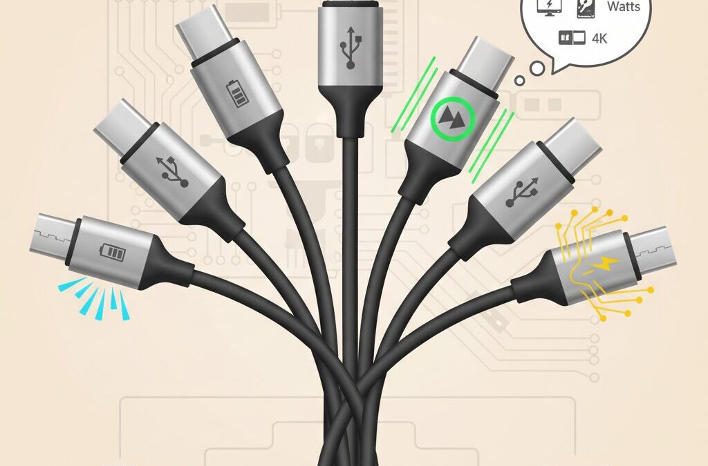
At first glance, USB-C looks like the long-awaited answer to cable chaos. The connector shape is identical across smartphones, laptops, monitors, and accessories, promising a single cable for everything. However, this visual uniformity hides a deep technical divide between what different USB-C cables and ports can actually do. The result is a paradox: USB-C is universal in form, but fragmented in capability.
This gap exists because USB-C defines only the physical connector, not the performance. According to the USB Implementers Forum, the Type-C specification was intentionally designed as a flexible container that could carry multiple generations of USB data protocols, power delivery profiles, and even non-USB signals like DisplayPort. That flexibility accelerated adoption, but it also shifted complexity from manufacturers to users.
In practical terms, two USB-C cables that look and feel identical can behave in radically different ways. One may support only basic charging and USB 2.0 data at 480 Mbps, while another can handle 40 Gbps data transfers, dual 4K displays, and 240 W power delivery. The connector does not tell you the story; the internal wiring and certification do.
| Aspect | What the Shape Guarantees | What It Does Not Guarantee |
|---|---|---|
| Physical fit | Reversible, identical plug | Any minimum data speed |
| Power delivery | Basic negotiation via CC pins | High-wattage charging support |
| Extra functions | Potential for video and PCIe | Actual video or Thunderbolt support |
This design choice becomes clearer when looking at history. Earlier USB standards tied capability closely to connector shape: Type-A for hosts, Type-B or Micro-B for devices. USB-C deliberately removed that distinction, allowing any port to act as host, device, power source, or sink. Those roles are now decided dynamically through electronic negotiation, not physical form.
Industry experts often describe USB-C as a “language port” rather than a single protocol. Intel’s work on Thunderbolt, later integrated into USB4, reinforced this approach by layering extremely high-speed data and display tunneling on top of the same connector. The USB-IF has acknowledged in its guidelines that this layering is a major source of consumer confusion, especially when cables are marketed simply as “USB-C” without speed or power labels.
A concrete example emerged with the global shift to USB-C on flagship smartphones. Many users discovered that a newly purchased USB-C cable charged their phone perfectly but failed to output video to a monitor or transfer large files quickly. The assumption that “USB-C equals full functionality” turned out to be false. In most cases, the cable was designed for charging efficiency and flexibility, not high-bandwidth signaling.
From a manufacturing perspective, this divergence is rational. High-speed cables require additional twisted pairs, shielding, and stricter tolerances, which increase cost and stiffness. Charging-focused cables can omit those elements, resulting in thinner, softer, and cheaper products that satisfy the majority use case. The problem arises when both are sold under the same visual identity.
Until labeling and certification become more transparent, the burden remains on users to look beyond shape and branding. Understanding why USB-C is universal in appearance but not in capability is the first step toward making informed decisions—and avoiding the frustration of a cable that fits perfectly but falls short of expectations.
The Evolution of USB Standards and the Naming Confusion
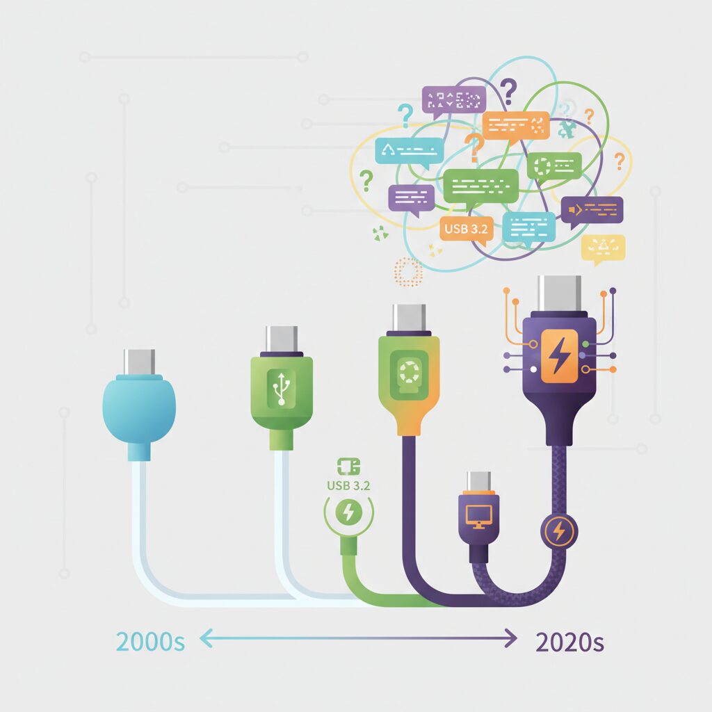
The history of USB standards has been a story of continuous technical progress paired with persistent naming confusion, and this gap has widened with the rise of USB-C.
Originally, USB versions were simple and sequential, such as USB 1.1 and USB 2.0, making it relatively easy for users to understand what they were buying.
However, as data transfer speeds accelerated, the USB Implementers Forum began renaming existing standards, and this decision still affects consumers today.
For example, what many users once knew as USB 3.0 was later rebranded as USB 3.1 Gen 1, and then again as USB 3.2 Gen 1.
Meanwhile, USB 3.1 Gen 2 became USB 3.2 Gen 2, even though the underlying performance characteristics remained unchanged.
The technical specifications stayed the same, but the names kept changing, and this is where much of the confusion originates.
According to USB-IF guidelines, this renaming was intended to align branding with evolving feature sets, yet in practice it blurred the distinction between speed tiers.
As a response, newer recommendations emphasize speed-based labels such as USB 5Gbps or USB 20Gbps, which directly communicate performance.
Despite this shift, legacy names continue to dominate packaging and online listings, especially in markets with long product lifecycles.
| Marketing Name | Former Technical Name | Max Speed |
|---|---|---|
| USB High-Speed | USB 2.0 | 480 Mbps |
| USB 5Gbps | USB 3.2 Gen 1 | 5 Gbps |
| USB 10Gbps | USB 3.2 Gen 2 | 10 Gbps |
| USB 40Gbps | USB4 / Thunderbolt 3 | 40 Gbps |
This complexity is amplified by the fact that USB-C refers only to the connector shape, not to data speed or power capability.
As a result, two cables that look identical can deliver vastly different performance, from basic charging to high-end workstation connectivity.
Industry experts from Intel and USB-IF have repeatedly pointed out that connector uniformity does not guarantee functional uniformity.
The evolution of USB standards, therefore, is not just a technical timeline but a lesson in how naming conventions can shape user experience.
Understanding this background makes it easier to navigate today’s USB-C ecosystem with realistic expectations and informed decisions.
Charging Speed vs Data Speed: Why They Are Not the Same
Many users naturally assume that a cable capable of fast charging must also be fast at data transfer, but in reality these two capabilities are designed and evaluated separately.
USB-C unifies the connector shape, not the internal wiring requirements, and this distinction explains why misunderstandings are so common. According to documentation published by the USB Implementers Forum, power delivery relies mainly on thick power conductors and protocol negotiation over the CC pins, while data speed depends on the presence and quality of high-frequency differential pairs.
This separation becomes obvious in real products. Many popular 100W or even 240W-rated charging cables on the market still use USB 2.0 signaling, capped at 480 Mbps. Manufacturers deliberately choose this design because omitting SuperSpeed data lanes makes the cable thinner, softer, and cheaper, without affecting charging speed at all.
| Aspect | Charging Speed | Data Speed |
|---|---|---|
| Main limiting factor | Current, voltage, E-Marker | Signal lanes, shielding |
| Typical optimization | Thicker power wires | Twisted, shielded pairs |
| Common misunderstanding | “Higher watts mean faster data” | “All USB-C cables are equal” |
A practical example is the iPhone 15 series. Even when connected with a 100W-rated cable, large ProRes video files transfer painfully slowly if the cable only supports USB 2.0. Reviewers and engineers repeatedly point out that the charging indicator looks perfect, yet the data pipeline is fundamentally narrow.
Understanding this difference helps buyers choose more rationally. A cable optimized for power excels at daily charging comfort, while a cable optimized for data targets creators and professionals. Confusing the two leads to frustration, not better performance.
Inside the Connector: Pin Layouts That Define Cable Performance
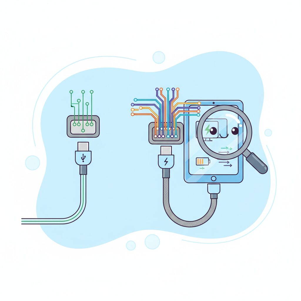
The performance of a USB-C cable is ultimately decided not by its jacket or branding, but by the microscopic architecture inside the connector itself. **Pin layouts determine which signals can physically pass through the cable**, setting hard limits on data speed, video output, and even charging behavior.
USB-C was designed with a maximum of 24 pins arranged symmetrically across two rows. This full pin count allows for multiple high-speed differential pairs, power delivery paths, and configuration channels. However, not every cable implements all of them, and this omission is intentional rather than accidental.
According to documentation published by the USB Implementers Forum, manufacturers are permitted to remove unused pins to reduce cost and improve flexibility, as long as the remaining configuration matches a defined use case. This design freedom explains why cables with identical connectors can behave so differently.
| Pin Group | Primary Role | Impact if Absent |
|---|---|---|
| D+ / D− | USB 2.0 data transfer | No data, charging only |
| TX/RX Pairs | SuperSpeed and USB4 | No high-speed data or video |
| CC Pins | Role and power negotiation | Unstable or unsafe charging |
| VBUS / GND | Power delivery | No charging |
In so-called charging-focused cables, only the minimum set of pins is populated. When viewed under light, the absence of metal contacts where SuperSpeed lanes should be visible is a clear indicator. **No amount of firmware or adapters can compensate for missing physical pins**, a point repeatedly emphasized by engineers interviewed in teardown analyses by Chargerlab.
Full-featured cables, by contrast, populate nearly all pin positions. This enables simultaneous high-speed data transfer and DisplayPort Alt Mode video output, because the necessary differential pairs physically exist. Dell and Intel both note in their technical briefs that video over USB-C is impossible without these dedicated lanes.
The key takeaway for enthusiasts is simple but powerful: **connector symmetry does not guarantee capability symmetry**. By understanding how pin layouts constrain signal paths, users can accurately predict real-world performance long before plugging the cable into a device.
E-Marker Chips and How Cables Communicate Their Limits
At the heart of modern USB-C cables lies a tiny but critical component called the E-Marker chip, and understanding its role changes how cables should be evaluated. An E-Marker is not a performance booster in itself but a communication device that allows the cable to declare its own limits before power or data fully flows. According to technical documentation published by USB-IF, this early-stage negotiation is fundamental to keeping both devices and cables within safe operating conditions.
When a USB-C cable is connected, the charger and the device first exchange signals over the CC line. If an E-Marker is present, it responds with structured information about the cable’s electrical and logical capabilities. This includes the maximum current it can safely carry, the voltage range it supports, and whether high-speed data modes are physically implemented. Without this digital self-identification, the system intentionally falls back to conservative defaults, even if the cable looks thick or premium from the outside.
| Cable characteristic | With E-Marker | Without E-Marker |
|---|---|---|
| Maximum current | Up to 5A (100W / 240W) | Limited to 3A (60W) |
| PD 3.1 EPR support | Explicitly reported | Not permitted |
| Host behavior | Enables high-power modes | Enforces safety limits |
This distinction explains a common real-world frustration. Even with a 100W charger and a power-hungry laptop, charging may stop at around 60W. In most cases, the bottleneck is not the charger or the device but a 3A cable lacking an E-Marker. USB-IF explicitly mandates that any cable intended to carry more than 3A must include an E-Marker, and compliant chargers are required to refuse higher currents if that confirmation is missing.
The importance of E-Marker chips has grown further with the introduction of USB Power Delivery 3.1 and its Extended Power Range. At up to 48 volts and 240 watts, electrical risks increase sharply, especially during hot-plugging. Industry analyses from companies such as Plugable and teardown reports by Chargerlab show that EPR-rated cables combine reinforced insulation with carefully programmed E-Markers. The chip effectively acts as a digital safety certificate embedded inside the connector, not a marketing label.
From a user perspective, the key insight is that cable intelligence matters as much as copper thickness. Two cables that feel identical can behave very differently once connected, because one can clearly communicate its limits and the other cannot. In an ecosystem where power levels now rival small appliances, E-Marker chips are how USB-C cables speak up for their own safety, and why silent cables are never trusted with maximum performance.
USB Power Delivery, 240W Charging, and What PD 3.1 Really Means
USB Power Delivery is often discussed as if it were a simple fast-charging label, but in reality it is a carefully designed negotiation protocol that prioritizes safety over raw speed. When a USB-C cable is connected, power does not immediately flow at high wattage. Instead, the charger, the device, and the cable itself communicate over the CC line to agree on voltage and current. According to the USB Implementers Forum, this negotiation happens before any high-power mode is enabled, which is why compliant cables rarely cause damage.
The jump from 100W to 240W is not just an incremental upgrade but a structural change in how power is delivered. With USB PD 3.1, the maximum voltage increases from 20V to 48V while the current remains capped at 5A. This new range is officially called Extended Power Range, or EPR, and it targets power-hungry devices such as gaming laptops, mobile workstations, and large monitors that previously required proprietary chargers.
| Power Range | Max Voltage | Max Power |
|---|---|---|
| SPR (PD 3.0) | 20V | 100W |
| EPR (PD 3.1) | 48V | 240W |
What is frequently misunderstood is that a 240W cable does not always deliver 240W. It simply declares that it can do so safely. The actual power is still determined by the connected devices. Engineers involved in USB-IF compliance testing have repeatedly emphasized that PD is conservative by design, meaning the system will always fall back to a lower profile if any element in the chain cannot confirm support.
PD 3.1 also introduces stricter requirements inside the cable itself. To handle 48V safely, EPR cables must meet tighter insulation and arc-prevention standards, especially during unplug events. Teardowns published by Chargerlab show additional spacing and protective components in certified 240W cables, which explains why they tend to be thicker and more expensive than older 100W models.
For consumers, the most practical takeaway is that PD 3.1 is about future-proofing rather than immediate speed gains. Even if today’s laptop only draws 140W, using a properly certified 240W cable ensures stable operation and compatibility with next-generation chargers. This design philosophy, rooted in USB-IF’s specifications, is what truly defines PD 3.1 beyond the headline number.
USB4 vs Thunderbolt 4: Understanding the Real Differences
When people see USB4 and Thunderbolt 4 written next to the same USB‑C port, it is natural to assume they are essentially identical. In practice, they share a common technical foundation, but their philosophies are quite different. **USB4 prioritizes flexibility and broad adoption, while Thunderbolt 4 prioritizes guaranteed performance and predictability**.
This distinction originates from governance. USB4 is standardized by the USB Implementers Forum, whereas Thunderbolt 4 is driven by Intel with a strict certification program. According to Intel’s technical documentation and USB‑IF compliance notes, Thunderbolt 4 can be understood as a tightly controlled profile built on top of USB4.
| Aspect | USB4 | Thunderbolt 4 |
|---|---|---|
| Maximum bandwidth | 20 or 40 Gbps depending on implementation | Always 40 Gbps |
| Display support | Required, but resolution and number vary | Minimum two 4K or one 8K display |
| PCIe tunneling | Optional | Mandatory |
| Certification model | USB‑IF compliance | Intel certification only |
The most critical real‑world difference lies in minimum guarantees. **A device labeled USB4 is not obligated to deliver the full 40 Gbps**, because the specification explicitly allows 20 Gbps implementations. This means that two USB4 laptops can behave very differently when connected to the same high‑speed SSD or docking station. Reviews by hardware analysts at BenQ and Lenovo have repeatedly shown measurable performance gaps between USB4 hosts.
Thunderbolt 4 eliminates this uncertainty. Intel requires every certified Thunderbolt 4 host to support 40 Gbps data transfer, PCIe at 32 Gbps, and robust display output. For professionals using external GPUs or fast NVMe enclosures, this consistency is often more valuable than raw peak specs.
Display behavior is another area where the gap becomes visible. USB4 mandates support for DisplayPort Alt Mode, but it does not define a strict minimum resolution. As a result, some USB4 systems allocate most bandwidth to data and only modest lanes to video. Thunderbolt 4, by contrast, enforces a baseline of dual 4K displays at 60 Hz, which Intel engineers have publicly emphasized as a usability requirement rather than a marketing feature.
Cable requirements further reinforce the difference in intent. USB4 cables may support 20 Gbps or 40 Gbps depending on construction and length. Thunderbolt 4 cables, especially certified active cables, must pass exhaustive signal‑integrity tests. Teardowns published by Chargerlab demonstrate that Thunderbolt 4 cables include retimers and heavy shielding that are not mandatory for USB4 cables.
From a buyer’s perspective, the decision often comes down to risk tolerance. **USB4 rewards informed users who read specifications carefully**, while Thunderbolt 4 rewards users who prefer a single logo that guarantees everything will simply work. This is why Apple, Dell, and other workstation vendors consistently choose Thunderbolt 4 for flagship models, even though USB4 is theoretically capable of similar performance.
In short, USB4 defines what is possible, and Thunderbolt 4 defines what is assured. Understanding this difference helps explain why two identical‑looking USB‑C ports can deliver dramatically different experiences in daily use.
Video Over USB-C: DisplayPort Alt Mode Explained
When people say that USB-C can output video, what they are really referring to is DisplayPort Alt Mode. This is not a bonus feature of all USB-C cables, but a specific way of repurposing high-speed data lanes inside the cable for video signals. **Understanding this distinction is critical to avoiding the common “no signal” problem when connecting monitors.**
DisplayPort Alt Mode works by temporarily reallocating some or all SuperSpeed differential pairs to carry native DisplayPort signals. According to technical documentation from the USB-IF and DisplayPort standard bodies, this approach avoids protocol conversion and preserves signal integrity, which is why image quality can match a direct DisplayPort connection.
| Requirement | Why It Matters | Practical Outcome |
|---|---|---|
| SuperSpeed lanes present | Video uses high-speed differential pairs | USB 2.0 cables cannot output video |
| Host DP Alt Mode support | GPU must expose DisplayPort over USB-C | Some USB-C ports are data-only |
| Cable signal quality | Video is sensitive to noise and loss | Cheap cables may cause flicker |
One subtle but important point is that **a cable does not “create” video capability**. The host device, such as a laptop or tablet, must explicitly support DisplayPort Alt Mode at the USB-C port. Major OEMs like Dell and Lenovo explain that even visually identical USB-C ports on the same device may differ internally, with only certain ports wired to the GPU.
Cable construction still matters, however. Full-featured USB-C cables include all high-speed pairs, making them physically capable of carrying DisplayPort signals. Thin, charge-focused cables often omit these pairs entirely, which is why they fail silently when used with monitors.
A reliable rule of thumb is that any cable rated USB 3.2 or higher is physically capable of DisplayPort Alt Mode, while USB 2.0-only cables are not.
Another overlooked aspect is bandwidth sharing. In DP Alt Mode, lanes can be split between video and USB data. For example, driving a 4K 60Hz display may consume most available lanes, reducing USB data speed. Display engineers at VESA have noted that this trade-off is a design choice, not a defect.
For users connecting high-resolution monitors, choosing a certified, full-featured cable is less about speed marketing and more about electrical completeness. **DisplayPort Alt Mode succeeds or fails at the physical layer**, and once that is understood, USB-C video becomes predictable instead of frustrating.
Brand Strategies and Quality Gaps in the Global USB-C Market
In the global USB-C market, brand strategy has become inseparable from quality differentiation, and this gap is widening rather than narrowing. While the connector shape is standardized, manufacturers intentionally segment products by hidden specifications, price tiers, and user experience priorities. This has created a market where **brand trust often substitutes for technical transparency**, especially for non-specialist consumers.
Premium brands tend to invest heavily in compliance and certification as a strategic moat. According to guidance published by the USB Implementers Forum, full USB-IF certification requires electrical testing, protocol validation, and logo licensing, all of which add cost and time. Established vendors such as Anker, Elecom, and Apple leverage this by positioning certified cables as “safe defaults,” even when many of their best-selling models deliberately remain USB 2.0 for flexibility and cost control.
| Brand Tier | Primary Strategy | Typical Trade-off |
|---|---|---|
| Premium Global | Certification and reliability | Higher price, limited flexibility |
| Mid-range Challenger | Feature visibility and UX appeal | Selective spec disclosure |
| Ultra-low Cost | Price dominance | Inconsistent compliance |
Mid-range challengers increasingly compete through visible differentiation rather than raw specifications. Power readout displays, braided or silicone jackets, and bold wattage labeling are designed to reassure enthusiasts without fully educating them. Industry teardown analyses from Chargerlab and commentary by engineers cited by Total Phase suggest that internally, many of these cables share similar USB 2.0 architectures despite very different branding.
At the bottom end of the market, quality gaps become structural risks. Investigations referenced by consumer safety agencies in Japan and the EU show that some unbranded cables omit proper resistors or shielding entirely. These products are not merely slower; they can destabilize power negotiation or accelerate connector degradation. As a result, **global USB-C branding is no longer just about speed or wattage, but about how much uncertainty a user is willing to tolerate**.
Safety Risks, Certification Marks, and How to Verify a Cable Yourself
Safety risks around USB-C cables are often underestimated, yet incident reports show that the cable itself can be the weakest link in an otherwise well-designed charging system. According to accident summaries published by Japan’s Consumer Affairs Agency and NITE, overheating and charring at the connector are recurring patterns, especially when high current flows through poorly manufactured cables. **The common trigger is not extreme wattage alone, but a mismatch between claimed capability and actual internal design.**
One critical factor is compliance with USB-IF certification. USB-IF, the organization that defines and enforces the USB standard, operates a compliance program that tests cables for electrical safety, signal integrity, and correct Power Delivery negotiation. Certified cables must pass checks on resistance, insulation, and protocol behavior before they are allowed to display official logos. In practice, this matters because devices trust what the cable reports. If a cable falsely advertises 5A capability, chargers may attempt to deliver 100W or even 240W, increasing heat and failure risk.
| Mark or Feature | What It Indicates | Why It Matters for Safety |
|---|---|---|
| USB-IF Certified Logo | Passed electrical and protocol tests | Reduces risk of overheating and mis-negotiation |
| Wattage Only (e.g. 60W, 240W) | Power capability, speed unspecified | Often USB 2.0; safe for charging if genuine |
| Thunderbolt Logo | Intel-backed 40Gbps compliance | Strict signal and power integrity requirements |
Certification marks alone, however, are not a magic shield. Counterfeit logos and vague packaging still exist, particularly in low-cost segments. Experts from USB-IF and independent teardown labs such as ChargerLAB consistently point out that **the presence of an E-Marker chip is the real dividing line for high-power safety**. For currents above 3A, Power Delivery rules require an authenticated E-Marker response before higher modes are enabled. Without it, compliant chargers will cap output, but non-compliant chargers may not, creating dangerous ambiguity.
Users can also perform basic verification themselves without specialized lab equipment. Visual inspection remains surprisingly effective. If a cable is marketed for 100W or 240W but feels extremely thin and lightweight, skepticism is warranted. High-current cables require thicker power conductors to limit resistance and heat. Another simple check is the connector printing. **Cables that show wattage without speed markings are usually charge-focused designs**, which is not inherently unsafe, but should not be assumed to handle data or video reliably.
For more certainty, consumer-grade cable checkers have become popular among enthusiasts. Devices such as those produced by Bit Trade One can read E-Marker data, measure internal resistance, and show whether SuperSpeed lanes are actually wired. This turns abstract specifications into observable facts and helps identify degradation over time. Studies and field tests show that as cables age, resistance can rise due to conductor fatigue or corrosion, directly increasing heat under load.
Ultimately, verifying a USB-C cable is about aligning trust with evidence. Certification marks provide a baseline, authoritative guidance from USB-IF defines the rules, and user-side checks confirm reality. In a market where one connector shape hides vastly different electrical behaviors, this layered approach is the most reliable way to protect both devices and users.
参考文献
- ZDNET:The best USB-C cables for the iPhone 15: Expert tested
- USB Implementers Forum:USB Type-C Cable Logo Usage Guidelines
- Anker Blog:Are All USB-C Cables the Same?
- Total Phase:What Is an E-Marker in a USB Type-C Cable and How Does It Work?
- Plugable Technologies:What Is 240W USB Extended Power Range (EPR)?
- Dell:Guide to DisplayPort over USB-C